Current output 1. Brief Introduction
1.1 Overview
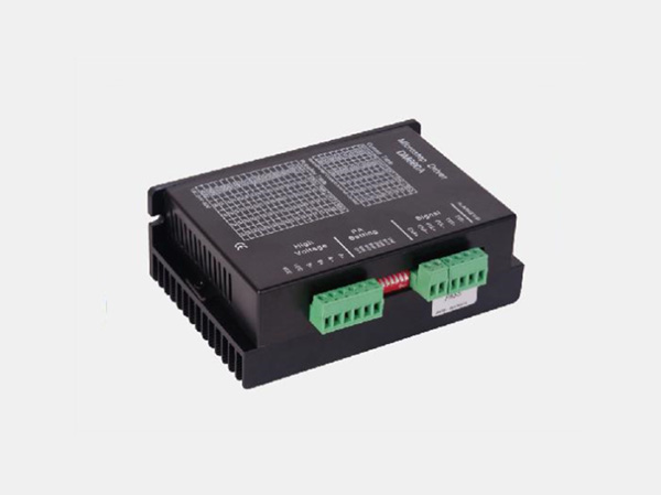
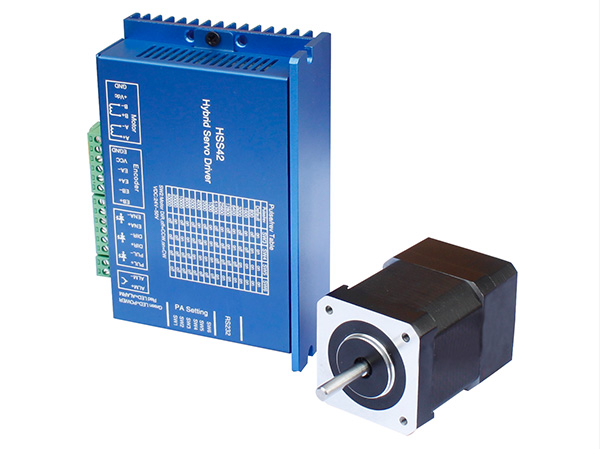
The 3HSS2260 is a hybrid high power stepper servo driver. It fits the 86(NEMA34) and 110(NEMA42) three-phase stepper motor. Compared to the traditional open-loop stepper driver, this stepper servo driver can completely avoid the stepper motor lost step problem, the high speed torque decrease is extremely lower than the open-loop stepper driver, greatly enhance the performance and torque of high speed motor. The driver current can be automatic controlled based on the load, it effectively restrain the temperature rise of the motor, extend the motor working life. Build-in position and alarm signal output are convenient for host computer to monitor and control the motor running state. The function of over position error alarm ensure the equipment working safely. It is the ideal replacement and upgrade of traditional open loop driver, and it is also with part functions ofAC servo system, price is only half of theAC system.
1.2 Features
★ 32-bit DSP and vector closed-loop control technology
★ Without losing step, high accuracy in position
★ Improve the motor output torque and working speed
★ Variable current control technology, restrain motor temperature rise
★Adapt to variety of mechanical load conditions(including low-rigidity pulleys), no need to adjust the gain parameter
★ Smooth and reliable moving, low vibration, great improvement in accelerate and decelerate
★ The ability of zero speed static without vibration
★Adapt to 3-phase 86(NEMA34) and 110(NEMA42) hybrid servo motor
★ Maximum step-pulse frequency 200KHZ
★ Micro step 200-65535 pulse/rev
★ Voltage rangeAC150-220V
★ Over current, over voltage and over position protection
★ Six digital tube display, easy to set parameters and monitor the motor running state
1.3Applications
It is suitable for the automation equipment and instrumentation which require large torque, such as: engraving machine, sewing machine, wire-stripping machine, marking machine, cutting machine, laser photo composing machine, plotting instrument, numerical control machine tool, automatic assembly equipment and so on. It is with good performance in the equipment with little noise and high speed.
2. Technical Index
Input Voltage | AC150~220V (Typically use 220VAC) |
Current output | Peak 6.0A(current variable based on load) |
Logic Current Input | 7~20mA |
Frequency | 0~200KHz |
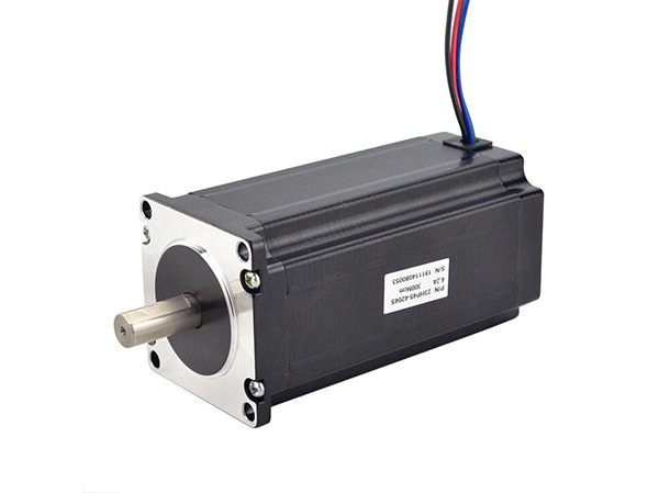
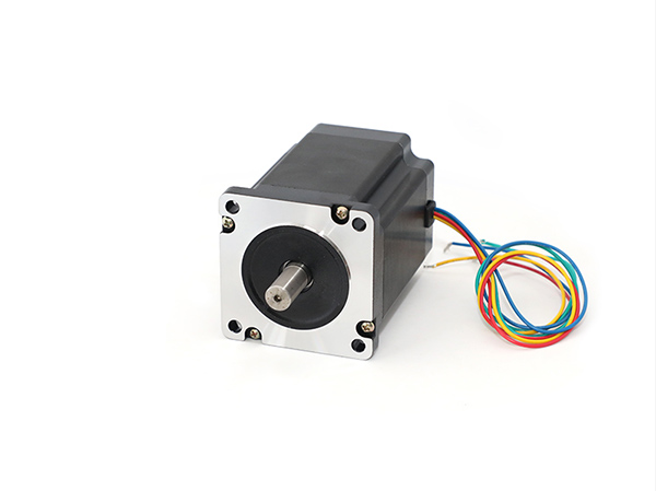
Suitable motor | 3-phase NEMA34 and NEMA42 hybird servo motor |
Encoder Resolution | 1000 |
Insulation Resistance | >=500MΩ |
2.2 Environment Index
Cooling Method | Natural cooling or forced air cooling |
Working Environment | Avoid dust, oil fog and corrosive gasses |
Working Temperature | 0~50℃ |
Humidity | 40~90%RH |
Vibration | 5.9m/s 2 Max |
Storage Environment | -20℃~65℃ |
Weight | Approximate 1500g |
2.3 Mechanical Specification

3.Ports Interface
3.1 Power Interface Ports1
Port | Symbol | Definition | Remark |
1 | L | Motor power Connector to 220AC | |
2 | N | ||
3 | NC | Not Connected | |
4 | BR | Braking Resistor | External braking resistor connected between Br and P+ |
5 | P+ | DC Busbar Voltage |
3.2 Power Interface Ports2
Port | Symbol | Definition | NEMA34 | NEMA42 |
1 | U | Motor Connection Port U | Red | Black |
2 | V | Motor Connection Port V | Black | Brown |
3 | W | Motor Connection Port W | Blue | Blue |
4 | PE | Ground | yellow | yellow |
5 | L | Controller power Connect to 220VAC | Range AC150-220V | |
6 | N | |||
3.3 Control Signal Interface Ports(44 Pins DB)
Port | Symbol | Definition | Remark |
3 | PUL+ | Pulse Signal Input + | |
4 | PUL- | Pulse Signal Input - | |
5 | DIR+ | Direction Signal Input + | |
6 | DIR- | Direction Signal Input - | |
7 | ALM+ | Alarm Signal Output + | |
8 | ALM- | Alarm Signal Output - | |
9 | PEND+ | Position Signal Output + | |
10 | PEND- | Position Signal Output - | |
11 | ENA+ | Enable Signal Input + | |
12 | ENA- | Enable Signal Input - | |
23 | OA+ | Encoder A Output | Encoder A,B,Z Signal differential drive(26LS31) output, non-isolated output. If the motor only with A,B two channel encoder, then ignore Z channel. |
24 | OA- | ||
25 | OB+ | Encoder B Output | |
26 | OB- | ||
27 | OZ+ | Encoder Z Output | |
28 | OZ- |
29 | CZ | Encoder Z open collector output | |
30 | GND | Ground |
3.3.1 Signal Output Interface Ports(Pend&ALM)
Pend and ALM signal output circuit use Darlington optocoupler, it can be connected with the relay or optocoupler. Note the following points:
★ Use a power supply to provide the power to the reply or optocoupler, the driver will be burned if the power supply is misconnected.
★ Power supply Maximum 25VDC, Maximum current 50mA.
★ If using inductive load such as a relay, a diode must be parallel with the inductive load, and if the polarity of the diode is reversed, the driver will be damaged.
★ When turned on, there is about 1V or so pressure drop, it can not meet TTL low level requirements, so it can not be connected with TTL current.

3.3.2 Signal Input Interface Ports(PUL, DIR, ENA)
★ Connections to Differential Signal

★ Connections to Common Anode

★ Connections to Common Cathode

5V signal input. If 12V signal input, additional 1KΩ resistor need to be connected. If 24V signal input,Additional 2KΩ resistor need to be connected.
3.4 Encoder Signal Input Interface Ports(15 Pins DB)
Port | Symbol | Definition | Remark |
1 | EA+ | Encoder A+ Input | If the motor only with A,B two channel encoder, then ignore Z channel. |
11 | EA- | Encoder A- Input | |
2 | EB+ | Encoder B+ Input | |
12 | EB- | Encoder B- Input | |
7 | EZ+ | Encoder Z+ Input | |
8 | EZ- | Encoder Z- Input | |
13 | VCC | +5V | |
3 | GND | Ground |
3.5 RS232 Communication Interface Ports
Port | Symbol | Definition |
1 | NC | Not Connected |
2 | +5V | For External HISU |
3 | TxD | RS232 Transmission Port |
4 | GND | Ground |
5 | RxD | RS232 Receiving Port |
6 | NC | Not Connected |
4. Wiring
4.1 Typical Wring Diagram

5. Parameters
5.1 Parameter Configure
Code | Definition | Range | Default Value | Remark |
PA0 | Power On Display | 0~7 | 0 | |
PA1 | Control Mode Selection | 0~1 | 1 | 0-Open loop, 1=Closed loop |
PA2 | Current Loop Kp | 1000 | Prohibited to Modify | |
PA3 | Current Loop Ki | 200 | Prohibited to Modify | |
PA4 | Position Loop Kp | 0~1000 | 300 | |
PA5 | Speed Loop Kp | 0~1000 | 400 | |
PA6 | Speed Loop Ki | 0~300 | 80 |
PA7 | Micro Steps Setting | 200~65535 | 4000 | |
PA8 | Encoder Resolution | 4000 | 1000 lines (4 times) | |
PA9 | Position Error Limit | 40~65535 | 1000 | |
PA10 | Holding Current Percentage | 0~80 | 30 | Unit: 100MA |
PA11 | Closed Loop Current Percentage | 1~80 | 60 | Unit: 100MA |
PA12 | Motor Type Selection | 0-2 | 0 | No need to select |
PA13 | Filtering Time | 0~1500 | 60 | Unit: 66.7μs |
PA14 | Enable Level | 0/1 | 1 | |
PA15 | Alarm Level | 0/1 | 0 | |
PA16 | Pulse Mode Selection | 0/1 | 0 | 0-PUL/DIR 1-CW/CCW |
PA17 | Pulse Edge | 0/1 | 0 | |
PA18 | Motor Rotation Direction | 0/1 | 0 | |
PA19 | JOG Speed | 1~600 | 120 | Unit: rpm |
PA20 | PEND Mode Section | 0/1 | 0 | |
PA21 | PEND Level | 0/1 | 0 | |
PA22 | Acceleration | 1~2000 | 200 | Unit: r/s^2 |
PA23 | deceleration | 1~2000 | 200 | Unit: r/s^2 |
5.2 Parameter Description
Code | Definition | Description | Range |
PA0 | Power On Display | When the driver is powered on, the display shows: ★ 0:Position tracking error ★ 1:Motor speed ★ 2:Given speed ★ 3:Feedback Pulse ★ 4:Given Pulse ★ 5:Given Current ★ 6:Error code ★ 7:Busbar voltage | 0~7 |
PA1 | Control Mode Selection | ★ 0: Open loop Mode: Receiving the signals only from the signal input ports, the motor is open loop controlled by the driver. Motor current is depending on the holding current(PA10) ★ 1: Closed loop mode: Receiving the Signals both from the signal input ports and the encoder, the motor position is closed loop controlled by | 0~1 |
the driver. Motor current is automatic changed based on the load | |||
PA2 | Current Loop Kp | Prohibited to Modify | |
PA3 | Current Loop Ki | Prohibited to Modify | |
PA4 | Position Loop Kp | ★ The higher value setting, the higher gain and the greater stiffness, and the smaller position lag under the same frequency command pulse condition. But too large value, may cause oscillation unstable system. The value setting depends on the load. | 0~1000 |
PA5 | Speed Loop Kp | 0-1000 | |
PA6 | Speed Loop Ki | 0-300 | |
PA7 | Micro Steps Setting | 200-65535 | |
PA8 | Encoder Resolution | ★ encoder line is 1000 lines, the PA8 default value is 4 times of the encoder lines | |
PA9 | Position Error Limit | ★ At closed loop and JOG mode, if the position error exceed the setting value, the driver will go into position error alarm. | 40~65535 |
PA10 | Holding Current | ★ Holding current=setting value*100MA | 0~80 |
PA11 | Closed Loop Current | ★ Closed loop current=setting value*100MA | 1~80 |
PA12 | Motor Type Selection | No need to select | |
PA13 | Filtering Time | Filtering Time=setting value*66.7μs | 0-1500 |
PA14 | Enable Level | ★ 0:When ENA input optocoupler transistor is OFF (cut off), motor is enable; When ENA input optocoupler transistor is ON (conductive), motor is free. ★1:When ENA input optocoupler transistor is ON (conductive), motor is enable; When ENA input optocoupler transistor OFF (cut off), motor is free. | 0~1 |
PA15 | Alarm Level | ★ 0:When alarm,output optocoupler transistor is ON (conductive); When normal working, output optocoupler transistor is OFF (cut off) ★ 1:When alarm,output optocoupler transistor is OFF (cut off); When | 0~1 |
normal working, output optocoupler transistor is ON (conductive) | |||
PA16 | Pulse Mode Selection | ★ 0:PUL/DIR mode ★ 1:CCW/CW mode | 0~1 |
PA17 | Pulse Edge | ★ 0:Normal ★ 1:Input command pulse reverse polarity | 0~1 |
PA18 | Motor Rotation Direction | ★ 0:motor clockwise rotation ★ 1:Anticlockwise rotation | 0~1 |
PA19 | JOG Speed | 1~600 | |
PA20 | PEND Mode Section | ★ 0:PEND as position output signal. ★ 1:PNED as brake output signal. | 0~1 |
PA21 | PEND Level | ★ 0:When positioning or braking OK, output optocoupler transistor is ON (conductive); otherwise output optocoupler transistor is OFF (cut off) ★ 1:When positioning or braking OK,output optocoupler transistor is OFF (cut off); otherwise output optocoupler transistor is ON (conductive) | 0~1 |
PA22 | Acceleration | Unit: r/s^2 | 1-2000 |
PA23 | Deceleration | Unit: r/s^2 | 1-2000 |
6. Alarm Function
6.1 Alarm Configure
ALM Code | Alarm Definition | Description |
-- | Working OK | |
1 | Over current | Motor current is too high |
2 | Over voltage | Main circuit power voltage is too high |
3 | Position deviation error | The position deviation exceeds the set value. |
4 | EEPROM fault | EEPROM fault |
6.2 Processing Method to Alarms
ALM Code | Alarm Definition | Reason | Processing method |
1 | Over current | Driver U, V, W short circuit. | Check the wiring. |
Grounding problem | Check ground. | ||
Motor insulation is damaged | Change a new motor. | ||
Driver is damaged | Change a new driver. |
2 | Over Voltage | When the power is turned on, the voltage is too high or too low. | Check the input power. |
The braking resistor wiring is sudden disconnected when the motor is running. | Rewiring. | ||
The braking resistor or braking transistor is damaged. | Change a new driver. | ||
3 | Position deviation error | When control power is turned on, circuit board is damaged. | Change a new driver. |
If motor U, V, W wrong wring or encoder wrong wring, the motor will be reverse running or not working, | Rewiring. | ||
Encoder is damaged | Change a new driver. | ||
The position deviation value range is too small. | Increase the position deviation value range. | ||
Position loop Kp is too low. | Increase the position loop Kp value. | ||
Insufficient torque. | Reduce the load or change a higher torque motor. | ||
Command pulse frequency is too high. | Reduce the frequency. | ||
4 | EEPROM fault | Chip or Circuit board is damaged. | Change a new driver. |
There is interference in the process of reading and writing EEPROM. | Restore the default parameters. |
7. Display and Panel
The panel is composed by 6 LED digital tube displays and 5 buttons
including ←、↑、↓、S(Shift)、ENT.
‘←’: Exit or Cancel
‘↑’: Increase or Next
‘↓’: Decrease or Previous
‘S’: Left shift digits

ENT’: Enter or Confirm
7.1 Main Menu Display
The operation mode is selected from the main menu. There are 4 operation mode: monitor mode, parameter setting, parameter management and JOG mode. Press the button ↑ and ↓ to change the mode, press the button ENT to enter the sub menu, press button ← to back to the main menu.

7.2 Sub Menu Display
7.2.1 Monitor Mode
Choose ‘dP-’ from the main menu, press button ENT to the monitor mode. There are 8 display status, press button ↑ and ↓ to choose the status, press button ENT to show the exact value.

7.2.2 Parameter Setting
Choose ‘PA-’ from the main menu, press button ENT to the parameter setting mode. There are 23 parameter codes from PA01 to PA23, press button ↑ and ↓ to choose the parameter code, press button ENT to show the parameter value. Press button ↑ and ↓ can modify the values. Button S can left shit the digits, and press button ↑ and ↓ to increase or decrease the shining digit. Press button ENT can confirm the modification. If you do not satisfy the modified value, do not press button ENT instead to press button ← to back to the original value.

7.2.3 Parameter Management
Parameter management mainly process the operation between parameter configure and EEPROM. Choose ‘EE-’ from the main menu, press button ENT to the parameter management mode. There are 3 modes: EE-Set, EE-rd and EE-dEF.
EE-Set: ‘parameter write into’, means write the parameters into EEPROM area. If users only modify the parameters, but do not write into the EEPROM area, the modified parameter will not be stored, it will restore the original value when power on next time. But if the parameter write into the EEPRPOM area, it will be the modified value when power on next time.
EE rd: ‘parameter read’, means read the parameter in EEPROM area to RAM area. This process will be executed once on power.At the beginning, the parameter value of the RAM space is the same as in the EEPROM area. But when user changes the parameters, it will change the RAM space parameter values. if the user is not satisfied with the modified values or the parameter values is disturbed, the parameter read operation can read the parameter in EEPROM area again in to RAM space.
EE-dEF: ‘factory reset’, means restoring the default value to RAM space, and meanwhile write into EEPROM area. The operation can be used when the users disturb the parameters and can not work properly.
Take EE-Set as an example: Choose the mode EE-Set, press the button ENT and hold 3 seconds, the display show ‘Start’, that means the parameters are writing into the EEPROM, after 1-2 seconds, if EE-Set operation is successful, the display will show ‘Done’, if the operation is failed, the display will show ‘Error’. Press button ← can be back to the main menu.

7.2.4 JOG Mode
JOG mode: set PA1=2, let the control mode to be JOG mode. Set the JOG speed by PA19, and setting JOG speed acceleration and deceleration by PA22 and PA23. Choose the JOG mode at the main menu. Press button ↑and hold, the motor will run at the JOG speed, Release button ↑, the motor will stop and hold on 0 speed. Press button ↓ and hold on, motor will run in reverse. Release button ↓ , the motor will stop and hold on 0 speed.
Website
Products
Contact Us
Mobile