1. Instruction
1.1 Overview
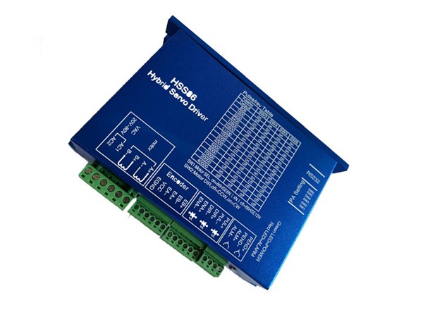
HSS86 is 2 phase nema 34 series hybrid stepper servo driver. It adopts new generation 32 bit DSP and vector control technology, which can avoid the stepper motor losing steps and ensure the accuracy of the motor. The torque reducing is much lower than open loop stepper motor when it is at higher speed. The high speed performance and torque are enhanced in a great extent. Meanwhile the current control is based on the load, that can reduce the motor temperature rising effectively, then can extend the using life of the motor. The build-in place in position and alarm output signal can help the upper monitor to monitor and control. The function of position ultra difference alarm can ensure the machine work safely. The closed loop system is an ideal improvement and a good replacement of open loop system, Besides that, it also have some function ofAC servo motors, but price is just half of AC servo.
1.2 Features
1.2.1 Stepper motor closed loop system, never lose step.
1.2.2 Improve motor output torque and working speed.
1.2.3Automatic current adjustment based on load, lower temperature rising.
1.2.4 Suitable for all mechanical load conditions (include low rigidity belt pulley and wheel), no need to adjust gain parameter.
1.2.5 Motor work smoothly and low vibration, high dynamic performance at acceleration and deceleration.
1.2.6 No vibration from high speed to zero speed
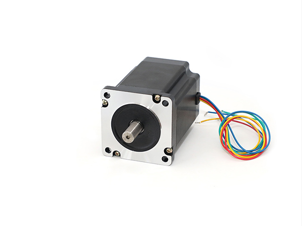
1.2.7 Drive nema 34 series 4N.m, 8N.m, 12N.m closed loop stepper motor.
1.2.8 Pulses response frequency can reach 200KHZ
1.2.9 16 kinds microsteps choice, highest 51200microsteps/rev.
1.2.10 Voltage range: AC24~80V or DC30V~110V
1.2.11 Over-current, over-voltage and position ultra difference protection function.
1.3Applications
Closed loop stepper system can be applied to all kinds small automatic equipment and Instruments, such as engraving machine, special industrial sewing machine, stripping machine, marking machine, Dispensing machine, cutting machine, laser phototypesetting, graph plotter, NC machine, automatic, assembly equipment and so on.
2. Electrical, mechanical, environment Parameter
2.1 Electrical Parameter
Logic input current | 7~20mA |
frequency | 0~200KHz |
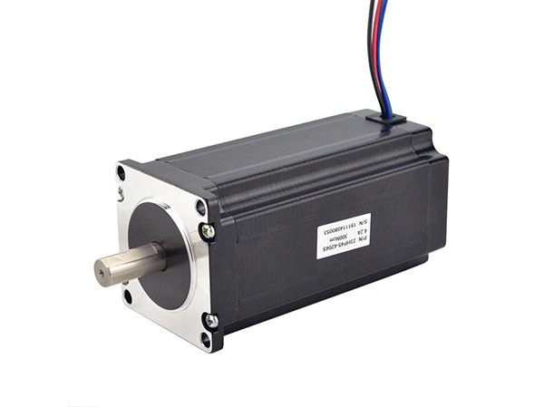
Suitable motor | 86HSE12N,86HSE8N,86HSE4N |
Encoder lines | 1000 |
Insulation resistance | >=500MΩ |
2.2 Environment Parameter
Cooling method | Natural or radiator | |
Operating environment | Operating Occasions | try to avoid dust, oil, corrosion gas |
Operating temprature | 0~50℃ | |
Operating humidit | 40~90%RH | |
virbration | 5.9m/s²Max | |
Storage temperature | -20℃~65℃ | |
Weight | About 560g | |
2.3 Installation Dimension 152mm*98mm*53mm

3. Driver connector, indicator and wiring diagram
3.1 motor and power supply input port
Port NO. | Motor Wire color | ||
1 | A+ | A phase winding + | red |
2 | A- | A phase winding - | green |
3 | B+ | B phase winding + | yellow |
4 | B- | B phase winding - | blue |
5 | AC1 | Input voltage | AC20~80V or DC30~110V |
6 | AC2 |
3.2. Encoder input port
Port NO. | Encoder Wire color | ||
1 | EB+ | Encoder B phase input+ | yellow |
2 | EB- | Encoder B phase input- | green |
3 | EA+ | Encoder A phase input+ | black |
4 | EA- | Encoder A phase input- | blue |
5 | VCC | Encoder voltage(+5V) | red |
6 | EGND | Encoder Grand(0V) | white |
(The encoder wires misconnected will lead to the damage of driver or encoder.)
3.3. Signal controller port
Port NO. | |||
1 | PUL+ | Pulse input + | If the signal control voltage is +5V, then the signal control input port do not need to connect an extra resistance. If the signal control voltage is +12V, then the signal control input port need to connect to a 1K resistance. If the signal control voltage is +12V, then the signal control input port need to connect to a 2K resistance. |
2 | PUL- | Pulse input - | |
3 | DIR+ | Direction input + | |
4 | DIR- | Direction input - | |
5 | ENA+ | Enable input + | |
6 | ENA- | Enable input - | |
7 | PEND+ | Position signal output+ | OC output, closed indicate finish the position, open circuit indicate position is not finished. |
8 | PEND- | Position signal output- | |
9 | ALM+ | Alarm signal output+ | OC output, there is alarm signal when closed, no alarm signal when open circuit. |
10 | ALM- | Alarm signal output- |
3.4.Switch setting
SW1:The choice of the motor. on=86HSE8N、86HSE4N , off=86HSE12N
SW2:Rotate direction setting.on=CW,off=CCW.
SW3、SW4、SW5、SW6:Microstep setting
Micorstep/rev | SW3 | SW4 | SW5 | SW6 |
Default(400) | on | on | on | on |
800 | off | on | on | on |
1600 | on | off | on | on |
3200 | off | off | on | on |
6400 | on | on | off | on |
12800 | off | on | off | on |
25600 | on | off | off | on |
51200 | off | off | off | on |
1000 | on | on | on | off |
2000 | off | on | on | off |
4000 | on | off | on | off |
5000 | off | off | on | off |
8000 | on | on | off | off |
10000 | off | on | off | off |
20000 | on | off | off | off |
40000 | off | off | off | off |
3.5 .Status indication
PWR:power indicator light : When power is on, the green light is on.
ALM:Alarm indicator light: If the red light is flicker one time within 3 seconds, that means over current or interphase short circuit; If the red light is flicker twice within 3 seconds, that means over voltage; if the red light is flicker three times within 3 seconds, that means position ultra difference or the encoder connector is disconnected.
3.6 .Wire diagram

3.7 .Wires for Encoder
Standard wire length for encoder is 3 meters. ( Wire length can be customized.)
Website
Products
Contact Us
Mobile